
2022
See total ranking
Get this page as PDF
دژ صنعت پرشین
شرکت دژ صنعت پرشین یک شرکت سهامی خاص می باشد که دفتر مرکزی آن در تهران میدان ولیعصر خیابان شقایق پلاک 8 واحد 19 می باشد در سال 2022 قراردادهای قابل توجه داشته تعداد 122 عدد جرثقیل سقفی و 346 عدد بالابر تعمیراتی توسط این شرکت تولید شده است.دژ صنعت پرشین یک شرکت نوآورانه با محوریت جرثقیل های سقفی و ضد انفجار در ایران و کشور های همسایه بوده و دارای کادری فوق متخصص و عضو هیات علمی دانشگاه می باشد.

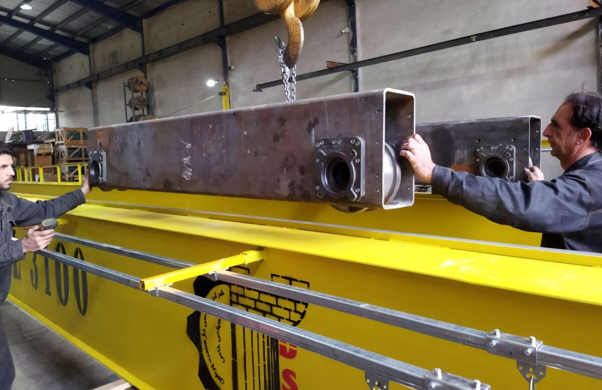

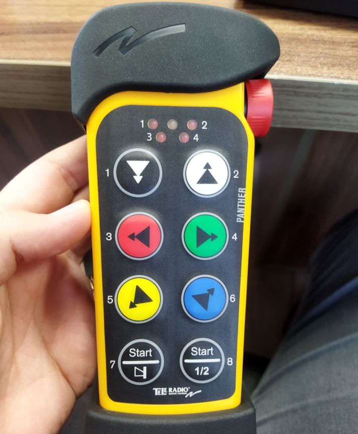


شرکت دژ صنعت پرشین نماینده رسمی کارخانه اشتال آلمان ( سازنده برتر نماینده اروپا در Crane) و تله رادیو سوئد ( سازنده برتر نماینده اروپا در ریموت کنترل های صنعتی و جویستیک) در منطقه می باشد. طی بررسی های دقیق انجام گرفته توسط تیم IMPROVMI شرکت های مرجع ملی نفت ایران ، پالایش و پخش فرآورده های نفتی ، شرکت ملی صنایع پتروشیمی ، شرکت ملی صنایع مس ایران از جمله مشتریان مطرح این سازنده می باشند.

ورود به سایت اختصاصی شرکت محترم دژ صنعت پرشین
Reference Document Assessment of Ability to Produce or Follow
ارزیابی بر توانایی تولید یا تبعیت از مدارک مرجع و پایه پروژه تعریفی


Compliance with the Employers Scope of Supplye
Test overal 120% of the nominal for static and 110% dynamic test according to FEM standards
Design according FEM standards
Compliance with the Employers Motor Datasheet
Compliance with the Employers Electrical and Control Equipment Datasheet
Compliance with the Employers General Arrangement and issue crane final Arrangement

Steel chosen from EN 10025 Table (S235 , S355 with min grade JR)
Calculation will be done according to FEM Standards
Proper Design Workshop weld and Use flanged by high-tensile bolt for joints transport to main site
Made up all box type structures with Steel Plates with Suitable Diaphragm and rolled Shape RFC
Forbidden to use plates with the thickness less than 8 mm for main frame
.M.A Rules sould be conform for welded joint working details
T-Bar should be connect to the Web and Top Plate for the joint below the trolley travel rail
AWS standard shall be considered for Welded Junctions
Rolled shape profile to be used for the Supporting Structures must be symmetric
Minimum Thichness shuold be considered 8 mm for main structure and 5 mm for secondary


In line butt height difference shall not exceed 5% of the minimum thichness
AWS B3.0 Specification Requirement shall be confirmed for Base Material and Welding procedure
The welds shall be carried out by welders who have passed the qualification tests
Bolt holes shall be made by drilling or by a punch Machine
Bolt shank length should be grather than part which is to be tightened and washer shall use.Sand Sa 2.1/2 and uniform inorganic galvanizing coating shall be considered for bolted joints
British Standards specifications BS3643 Part 1 & 2, ISO Metric screw threads shall be considred
Steel as Defined in the ASTM standards or similar shall be used
Bridge,Trolley Travel,Hoist,Hooks and Blocks shall be made according to standard
The hook shall be made from forged steel and no welding is permitted on the hooks
The Couplings shall be made from forged Material
Flexible couplings with brake in accordance with DIN 15431 Sall be employe between motor and GB
All drive shafts must be obtained from steel bar or tube and deflectin shall not exceed 1mm pm
All supports shall be in steel or spherical cast iron with rolling bearing
Minimum life time for bearings shall be 50000 hours
The drum shall be made with welded Steel plates normalized after welding according to din 15061
More basic design requiremens for Wire rope,Equalizer Sheaves,Load Cell,wheel,Rails,Buffers,Reducing Gears unit,Gear wheels,Rotating parts Protection Carter,Lubrication,Guarantee in improvmi booklet


A system will be set up that prevents all access that may endanger people or the crane
Any moving part, which may pose a danger to people, must be effectively protected and indicated
Provision for safe access of personnel to and around equipment for functions
All stairways giving access to the bridge, diver’s cabin, etc. shall have tread and a ratio or rise not exceeding 450 and width of at least 600 mm
Back protection shall consists of three vertical stringers interconnected by rings spaced at 600 mm interval. The wall of the ladder well opposite to the ring plane shall be located at a distance not exceeding 600 mm from these rungs
Deck shall be built, according to rules, at the heads of the bridge to facilitate maintenance of the collector shoes of the bridge and of the wheel assemblies, whenever the crane structure does not permit such maintenance from inside the crane. Access shall be ensured by means of a stair and irremovable hinged trapdoor. Opening of this trapdoor shall be such as to prevent any contact with moving parts and the personnel shall not be exposed to the hazard of empty space
All rotating members (couplings pulleys, gear, etc.) shall be protected by sturdy carters in plate. All heavy covers shall be provided with inspection windows. The carters of the driving and idle wheels of bridge and trolley shall be fitted with irremovable hinges. Large-sized protections and guards shall open horizontally to permit removal of the upper part during inspection without need to remove the lower part. All walking decks shall be in antiskid checkered plate with the exception of the walking deck formed by supporting box girders. For the walking decks outdoor buckle plate shall be used. The walking decks in very dusty environments shall be in sturdy grating having 20×20 mm max mesh. The floor plates shall be anchored to the supporting frame. Provision shall be made for handrails wherever necessary to prevent personnel from falling from elevated areas.
Access to trolley shall be easy and assured in all and anyone trolley position by means of a catwalk of at least 600 mm width, practicable and free from obstacles up to a height of 1800 mm from floor level. The walkways shall be provided with handrails and toe board in compliance with safety regulation on the outer side of the crane. Handrails with toe board shall be installed on the trolley sides. The distance between these handrails and the trolley gears shall be such as to provide easy access for maintenance purposes
These limit switch shall be mounted without varying the free space on the bridge and trolley and shall always leave a clearance of at least 600 mm along the runway. The mechanical components of power limit switches shall be suitably anchored so as to prevent their falling down in case of failure
All working parts and lubrication points in so far as possible are to be arranged for easy accessibility, convenience of operation, inspection, lubrication and ease of replacement with minimum downtime. Provision for access ladders/staircases will be made at the following location and wherever else found necessary: - Crane railway to crane walkway - Crane walkway to operator’s cabin - Crane walkway to power collector inspection platform where provided. - Crane walkway to wheel inspection platform where provided - Trolley floor to crane walkway


The crane will be designed in order to minimize maintenance and make unavoidable maintenance safe, quick and easy. In order to minimize the frequency of maintenance, the temporary table of inspection and maintenance of crane components, contained in the offer documentation, must be drawn up in terms of previous engineering experience and subsequent improvements. The final table, which will be coherent with the temporary one, will be included in the instruction and maintenance manual and will be contractually binding. Each crane component must be configured according to the following maintenance requirements: The components to be maintained and/or inspected must be easily accessible with minimum disassembly; all guards covering components must be hinged and have quick locking systems and stays for their open positions. Every component must be easy to handle and equipped with hooks to allow them to be properly balanced when lifted. Components which need frequent maintenance must be easily accessible and they must not need special tools
تمامی حقوقی این وب سایت متعلق شرکت رهام بنیان صنعت است.
SDG2000
ما یک تیم هستیم
انرژی و آب و هوا
طبیعت

Fair use donation
Disclaimer
Privacy statement


سبد خرید